Hanford Mills Museum Turbine & Slide Gate
- Amy Boyce

- Feb 16
- 3 min read
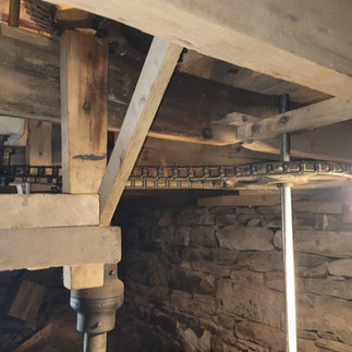
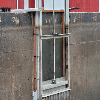
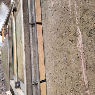
Millwright Jim Kricker and Husk, maintanced and repaired the slide gate for the penstock. Work included: Tarped and sandbagged head gate, pond was drained, built a sort of cofferdam, continually pumped, dug muck down to below the gate, pressure washed gate, assessed gate and grout, heat-dried grout and painted where accessible with Block and Wall Liquid Rubber Paint, measured, laid out and cut new white oak wood spacers, loosened bolts and slid in spacers, test fit and refined spacers’ fit, tightened bolts back to original positions, checked that the gate still slid/performed as desired, cleaned up.
In another scope of work, we repaired the turbine. The turbine's top and bottom plate of the scroll case had cracked due to too quickly closing of the butterfly valve, a sort of design flaw. This scope of work encompassed a comprehensive structural assessment, mechanical rehabilitation, precision fabrication phase, and full system recommissioning of the historic turbine and its control assemblies.
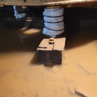
We began by excavating accumulated silt from the tail race to expose and evaluate the ✖-shaped timber footing and underlying plank platforms. Test boring confirmed the primary timber foundation and lower plank tiers to be in good condition. Missing leveling wedges were replaced. In parallel, we excavated and constructed a new stone footing for the Bray Valve support, layering stone, backfilling, and preparing black locust timbers with copper isolation barriers for long-term durability. The turbine runner and vertical drive were then lifted after disassembly of stop collars, and bearings. We inspected the runner—stabilizing minor blade damage—cleaned and assessed the lignum vitae thrust bearing, oil well and packing assembly, and vertical radial bearing, all of which were found to be in good condition. Bevel gears were cleaned and lubricated, gear mesh deficiencies were identified, and alignment conditions were corrected.
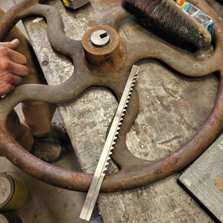
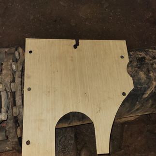
Major corrective work addressed historic fractures in the scroll case and deficiencies in the actuation system. The previously repaired top and bottom scroll plates—patched with an internal sleeve and exterior filler—were stripped and cleaned after removing a seized butterfly valve from its lower bearing. Evidence showed the turbine had shifted prior to earlier repairs; we repositioned it to proper alignment and machined material from the cast iron casing break to prepare for accurate new plate installation. The actuation strategy was redesigned to retain and improve the butterfly valve for controlled closure. Templates were created for new top and bottom repair plates, and key components—including the butterfly valve, control shaft, chains, sprocket, and salvaged large-diameter handwheels—were removed for off-site machining. Fabrication included CNC cutting the new top plate, welding flanges and studs, boring plates, milling a new bearing and packing sleeve, machining and keying a new valve control shaft, forging the upper control shaft to accept a square-drive handwheel, broaching a reclaimed larger handwheel, modifying the butterfly valve height, reducing the stop collar, and refinishing journals to ensure proper fit and durability.
On-site reinstallation required continuous pumping, precision fitting, and sequential mechanical integration. The new top and bottom plates were test-fit, drilled through the original scroll case, mechanically cleaned, sealed with two-part coal tar epoxy and marine adhesive sealant, and secured with stainless steel hardware and countersunk fasteners to ensure unobstructed valve travel. The butterfly valve was reinstalled with lubricated bearings, new upper and lower zerk fittings, neoprene blades, a custom lexan spacer, stepped and tapered keys, new packing and press collar hardware, and an upgraded larger sprocket and chain system to improve mechanical advantage. Control shafts were remachined and shimmed on-site, stop collars were added for redundancy, and both handwheel stations were reassembled, aligned, and clearly marked for safe operation. The vertical drive alignment was corrected by modifying the radial bearing height and stop collar; bevel gear mesh was improved by repositioning the wood gear under controlled rigging pressure after shaft-level measurements and tightening of the timber support frame. We installed the permanent locust penstock support frame with opposing wedges, tightened turbine footing bolts, lubricated the neck bearing, added seasonal freeze protection, and conducted controlled test runs. Sequential valve operation confirmed smooth engagement, improved gear mesh, reduced turning resistance, enhanced operator safety, and a fully stabilized, properly aligned turbine system ready for continued service.


Slide Gate Work Gallary


Comments